Xploration • Curation • Recommendation


A Brief Hobbyist Primer on Effects Pedal Circuits Fixed Resistors - in collaboration with Drunk Beaver's Vitalii Bobrov
FeaturedGuitar Gear ResourcesGuitar Pedal 101Iconic Gear


Key Points
Resistors were formalised by Georg Simon Ohm in 1827: V = I × R. Wirewound, carbon composition, carbon film, metal film and SMD formats followed. Pedals mainly use 0.25W through-hole or 0603 SMD resistors; metal film is low-noise with 1% tolerance, carbon film 5%.
4- and 5-band colours identify values. Common values include 10kΩ, 4K7Ω, 1kΩ, 100kΩ and 1MΩ. Resistors handle voltage division, biasing, tone shaping, pull-down/anti-pop duties and LED current limiting.
Mods include Fuzz Face 470/8K7 swaps, Tube Screamer 4K7-to-2.2K, Rat 470Ω-to-100Ω or 1K pot, and LPB-1 390Ω-to-100Ω. Consult a qualified tech before opening or modifying pedals.
This article was composed and assembled in collaboration with good friend Vitalii Bobrov of Drunk Beaver Pedals - a fantastic engineer, with an encyclopaedic knowledge of effects pedal components - which you can see in all his smart circuit builds.
This article focuses on Fixed vs Variable Resistors and Potentiometers - those will be covered in a follow-up article.
There are 6 Key Chapters to this project of differing length and detail.
Hopefully we have covered everything you need to know about Fixed Resistors, and how they apply to Guitar Effects Pedals!
CHAPTERS
- A Brief History of Resistors
- The Key Types Of Effects Pedal Resistors
- How a Typical Resistor Works
- Identifying Resistor Values
- Key Functional Applications for Fixed Resistors
- Smart Resistor Deployments and Mods in Specific Circuits (Fuzz Face etc.)
- Resistor Circuit Examples
1. A Brief History of Resistors
A QUICK NOTE!
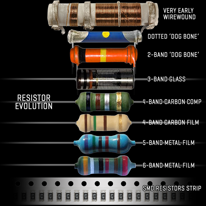
A few individuals on Social Media have accused me of AI Slop here! Where none of this article is AI, it took 2 weeks of research and cross referencing. And I trusted in a handful of Ebay vendors who all had 100% satisfaction ratings - that what they were selling were glass vacuum resistors, which can look unerringly close to Diodes. Glass resistors were definitely a thing, military spec - and fairly specialist - and indeed some looked pretty close to germanium diodes! Some more than others!
Mike Piera also called me out on 'AI content' - which this most definitely is not. But I have decided to change the core Glass Resistor image above for a more verifiable variant. All this is thoroughly researched and triangulated, and checked and cross-referenced as much as is possible - while there is always some room for error. For sake of clarity I have decided to update the image above to hopefully make it more palatable to those critics and gainsayers.
1827 Resistor Origins and Earliest WireWound Examples of ResistorsA
Resistors were originally conceptualised and formalised by Georg Simon Ohm in 1827. The author of Ohm's Law :
Voltage = Current × Resistance [ V = I x R ]
Long Iron and Copper Wires, were typically coiled around a cylinder - to add Resistance to Telegraph Systems. You can see an early example of a WireWound Resistor at the top of the above visual.
These evovlved to Nichrome Wire wrapped around Ceramic or Glass Cores - for high power, heavy electronics and power supply purposes.
1890's - 1960's : Carbon Composition Era
Carbon Comp (CCR) : Moulded from a mix of carbon powder and ceramic binder, these 'Dog-Bone' shaped resistors became standard for early vacuum-tube radios. See Blue and Orange Dog-Bone example in the above visual.
Pros & Cons : They were cheap and durable against high-voltage pulses, but noisy, with poor tolerance (low accuracy) and a tendency to drift. The use of Carbon Comp Resistors in Fuzzes will mean that those won't now sound the same as they did when they left manufacturing. Drift impacts not just tolerance, but also the resulting tone from that component.
Otis Boykin patented an improved, durable carbon resistor variant in the 1950s and 1960s used in guided missiles and radios.
Late 1920's Onwards : The Codification of Coloured Dots and Bands for Value Identification
Generally Resistor components were too small for the time to easily print legible values onto their sides. Instead the Radio Manufacturer's Association (RMA) helped codify a standard of colour markings which identified the value of each resistor.
The earliest variant of this was the Body-End-Dot or Dotted standard, which consisted of :
- Body Colour : The main body colour showed the first significant digit
- End Colour : A painted colour band on one tip indicated the second digit
- Center Dot : A small coloured dot in the middle served as the multiplier (power of ten)
- Default tolerance : Unmarked units carried an assumed ±20% tolerance
The RMA formally endorsed that standard around 1930-31, and then in following years the standard evolved first to 2 fully circular bands - as the dot was very directional - and said component wasn't always oriented toward the viewpoint of the engineer. With the all-around bands - a resistor could by identified from every angle.
The following years saw an evolution to 3 bands, then the now standard 4 and 5 band variants we see today. While we also have a 6 band variant - where the 6th band is the Temperature Coefficient - but those are very specialist and rare. You most commonly see 4 or 5 Band types nowadays. The codification of those standard has been variously updated including the first IEC 62 in 1952, and the latest 6th IEC 60062 iteration as recently as 2016.
You can see the common colour band identifier in Section 4 below!
1950's - 1960's : Film Resistors - Carbon Film and Metal Film
Carbon and Metal Film : Engineers coated ceramic rods with thin carbon or metal films instead of solid carbon blocks or coiled wires.
Stability : Metal film versions introduced in the 1950s offered vastly superior temperature stability, lower noise, and tighter tolerances.
1980's to Present : Surface-Mount and Modern Micro-Resistors [Thick and Thin Formats]
Thick and Thin Film : Thick and Thin film deposition techniques allowed microscopic resistive layers on ceramic substrates.
SMD revolution : The shift to Surface-Mount Technology (SMT) in the 1980s and 1990s shrank components down to fractions of a millimetre for modern electronics.
SMD Resistors come in 9 different sizes - ranging from the smallest 01005 (Metric 0402) at 0.4 × 0.2 mm, to largest 2512 (Metric 6332) at 6.3 × 3.2 mm - which are made for high current paths and applications.
There is and old myth that SMD Resistors are less durable. Primarily SMD components were developed for NASA space needs. The goal was to have smaller and at the same time - components that could survive huge physical overloads - so surface mount is more stable under vibrations, etc.
NOTE - that this article is mostly about the kind of Resistors you find in Effects Pedals and Amplifiers - so we're skipping over the larger, and square profile more industrial ones!
2. The Key Types Of Effects Pedal Resistors
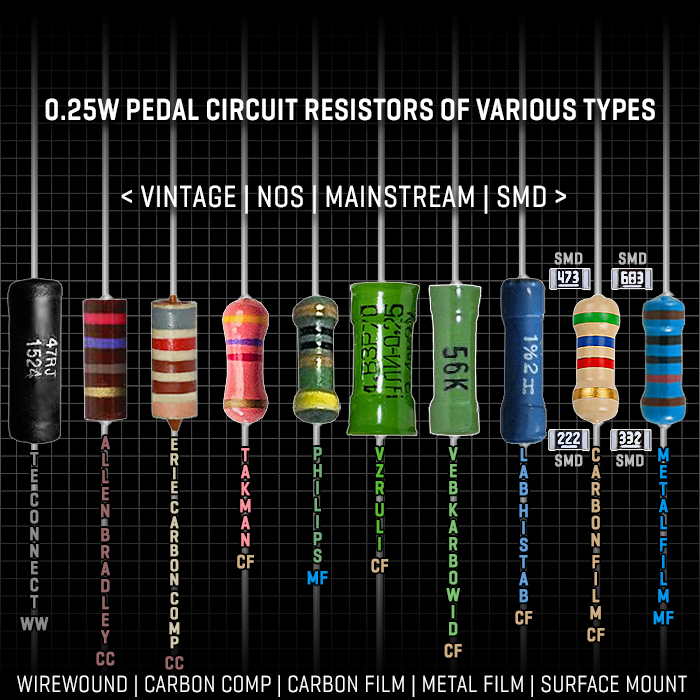
Note that I've updated the above and top visual, all resistor references should be correct now. The Internet can be something of a quagmire! Apologies for those slip-ups! And do continue to point out any errors you find!
So in contemporary Effects Pedals you will see either Through-Hole Blue and Tan Resistors - which are typically Carbon Film or Metal Film, but for some applications Carbon Comp too - which is the cheapest and least precise type. For high-fidelity / Audiophile applications - it's almost always Metal Film.
Effects Pedals typically use the 0.25W class of Resistors, which is what I'm focusing on here! Very occasionally 0.125W.
Vitalii added a note here that the standard has evolved somewhat of late - where Resistor Wattage nowadays has evolved to and is more likely to be at 0.4W and 0.6W.
So for hand-made pedals the Carbon Film and Metal Film types are the most common - in 6.3mm x 2.3mm format. Vitalii confirms that Metal Film is preferred because it has a typical tolerance of ±1%, while carbon ones are @ ±5%. But if you expect higher currents for example, then carbon ones would be better.
For machine-made Pedals - SMD Resistors are normally used - typically the 0603 (Metric 1608) format - at 1.6mm × 0.8mm.
Vitalii notes that the choice of SMD Resistors depends on available space and voltages/currents. Most common are 0603 / 0805 / 1206. 0402 is trickier because not every factory supports that size. 0603 or bigger are not a problem for hand soldering (Vitalii does that mainly on prototypes, but quite often, and finds that desoldering SMD is way easier than THD!
The above visual feature 3 contemporary THD Resistors and 4 x SMD ones, where the preceding 7 are :
- TE Connectivity Black WireWound type
- Allen & Bradley Dark Brown Vintage Carbon Comp type
- Takman Salmon Pink Carbon Film type
- Philps Dark Green Metal Film type
- VZR ULI Carbon Film type
- Veb Karbowid Carbon Film type
- Lab Histab Carbon Film Type
Several of the Vintage and NOS types are held to having desirable tonal characteristics - and are still in high demand. Not all Resistors are entirely to scale - as some of those older Vintage types can be a little larger than the common 6.3mm Length. This is just a subset of the kinds that appear in effects pedals.
There are scores of Resistor Manufactures which include the following notable sources (Vintage & Contemporary) :
- Allen-Bradley
- Amtrans
- Arcol
- Audio Note
- Bourns
- Caddock
- Charcroft
- Dale / Vishay
- Dayton Audio
- Erie
- Holco
- Jantzen
- Kiwame
- Koa Speer
- Lab Histab
- Mundorf
- Ohmite
- Panasonic
- Philips
- Shinkoh
- Susumu
- Takman
- TE Connectivity
- Veb Karbowid
- Vishay
- VZR ULI
- Xicon
- Yageo
MojoTone and HiFi Collective are typically good resources for Vintage / NOS / Audiophile Resistors. And Ebay can be pretty good - but you need to do your due diligence and exercise caution - as you don't always get what you think you ordered!
A note from Vitalii on 'Audiophile Resistors' - a bit on the Hi-Fi myths side - basically from an electronics perspective, a resistor is a parasitic component and is 'unavoidable evil'. But seriosly, measuring the difference between low PPM (Temperature Coefficient of Resistance) / Audiophile resistors in real circuit would always show that there would be way bigger sources of any noise. Instead of looking for magic resistors, designer should consider using as low a resistances as possible to reduce noise instead. A good example is a typical non-inverting amplifier with OpAmp 10k input + 100k feedback resistor - gives the same amount of amplification as 1k + 10k pair, a lower resistance pair would have less noise. Of course there other factors to consider and choose for balancing resistances. But at the same time, a way bigger source of noise would be OpAmp itself - for a lot of scenarios.
Brief Overview of Key THT / THD Resistor Types
WireWound : Original format coiled wire around ceramic cylinder - typically a more vintage standard, but there are still some specialist resistors of that type. Not as efficient or reliable as more modern 'Film' types!
Carbon Composition : Large, expensive, and noisy parts used mainly for authentic 1960s vintage mojo builds.
Carbon Film : A slightly noisier, warmer vintage choice with a 5% tolerance, coloured light brown.
Metal Film : The industry standard for modern builds; they are inexpensive, low-noise, and have a tight 1% tolerance.
The WireWound ones tend to be a little longer / larger, while as mentioned the standard format for Effects Pedals is normally the 0623 / DIN 0207 6.3mm x 2.3mm format!
Power Rating : Standard pedals run on very low power, making 1/4W (0.25W) through-hole resistors the ideal size.
The SMD / SMT Resistor Formats
- 01005 (Metric 0402): 0.4 × 0.2 mm – Used in ultra-compact RF and wearable tech
- 0201 (Metric 0603): 0.6 × 0.3 mm – Used in smartphones and tiny sensors
- 0402 (Metric 1005): 1.0 × 0.5 mm – Common in high-density mobile devices
- 0603 (Metric 1608): 1.55 × 0.85 mm – The general industry standard for consumer electronics
- 0805 (Metric 2012): 2.0 × 1.25 mm – Popular for general industrial boards and easy hand-soldering
- 1206 (Metric 3216): 3.2 × 1.6 mm – Used for higher power and better heat dissipation
- 1210 (Metric 3225): 3.2 × 2.5 mm – Found in power supplies and converters
- 1812 (Metric 4532): 4.5 × 3.2 mm – Used in motor controls and amplifiers
- 2010 (Metric 5025): 5.0 × 2.5 mm – Handles higher power loads
- 2512(Metric 6332) : 6.3 × 3.2 mm – The largest standard size, built for high current paths
In Machine-Made Pedals you typically see 0603 Formats - which are simplified to 1.6 x 0.8mm. While there are some hand-build pedals that use SMD Resistors also - and these tend to be 0805 (2.0 x 1.3mm) or 1206 (3.2 x 1.6mm) - which are somewhat easier to handle.
Thin Film vs Thick Film Resistors
Most resistor types come in Thin and Thick Film variants, including the SMD ones. The Thick ones are cheaper and less precise - with a best Tolerance of 1%, while the Thin format can reach just 0.1% Tolerance - which is incredibly precise! Typically Thin Film manufacturing is more precise, and uses a better Resistive Layer Composition - which delivers those refinements!
Vitalii adds that there is also a difference in PPM values (Temperature Coefficient of Resistance) which can result in more noise being generated.
The 'E SERIES' of Preferred Electronic Component Value Numbers - as applies to Resistors, Capacitors, Inductors, and Zener Diodes
The 'E series' is a system of preferred numbers (also called preferred values) derived for use in electronic components. It consists of the E3, E6, E12, E24, E48, E96, and E192 series, where the number after the 'E' designates the quantity of logarithmic value 'steps' per decade. This is essentially the spread of typical values stepped across a logarithmic curve.
Of those 7 E Series - the E24 one (5% Tolerance) is the one that is the most pertinent to Effects Pedal Resistors, where the curve of 24 stepped values follows the below sequence :
1.0, 1.1, 1.2, 1.3, 1.5, 1.6, 1.8, 2.0, 2.2, 2.4, 2.7, 3.0, 3.3, 3.6, 3.9, 4.3, 4.7, 5.1, 5.6, 6.2, 6.8, 7.5, 8.2, 9.1
In the same way - E3, E6, E12, E48, E96, and E192 - the digits indicate the number of variables for each set - from just 3 for E3 with a 40% Tolerance - through to 192 values with a 0.5% Tolerance.
Instead of manufacturing a Resistor for every single possible number, factories only produce these 24 specific sizes per E24 range. They are carefully spaced out so that, when factoring in a standard manufacturing margin of error, any exact resistance a circuit might need will always be covered by or extremely close to one of these standard parts.
This gives pedal builders and amp designers a predictable, universally available palette of parts to perfectly dial in a circuit's gain, EQ, and volume without needing to custom-manufacture a unique resistor for every tiny tonal tweak.
Typically Resistor values are handled in the next Section :
3. How a Typical Resistor Works
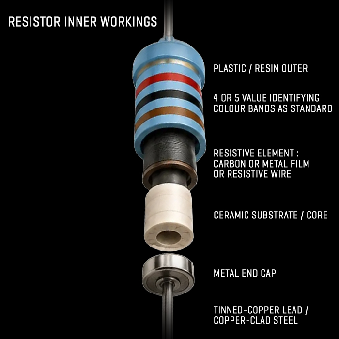
The mechanics of a typical Resistor haven't really changed that much since the very original 1827 WireWound Cylinder Types.
You still have an Insulating Inner Core or Substrate - typically made of Ceramics.
You then have the Resistive Layer / Element - which very originally was the Coiled / Wrapped Wire around the Cylinder, while later evolutions consisted of Carbon and Metal Film - which could be delivered very Precisely in ever more diminutive Thin Layer Formats.
So the Ceramic Core or Substrate comes first upon which you wrap or lay down the Metal / Carbon Film Layer, protected by some sort of Plastic or Resin Outer / Casing, and then with Metal End Caps at either end - which are connected to high conductive wire leads made of either Tinned-Copper, or Copper-Clad Steel.
So the most typical format is cylindrical - particularly for THT devices, while the more squared off industrial and SMD variants work more as flat layers. As you've seen in the previous sections - the size of those SMD components can be incredibly tiny - as little as 0.4 × 0.2 mm.
Generally though this is pretty basic physics - where material science has helped improve and miniaturise the format - while the basic mechanic is always the same.
Properly deployed Resistors can and do last a lifetime. They're very robustly structured and take a fair bit of manhandling. But you need to use the appropriate Power Supply / Wattage per type - as if you expose a Resistor to more current than it was designed for - it will Melt!
So as long as you've used the right values and the right power / wattage type - you should never need to replace a resistor in a circuit. While Capcitors, Diodes and Transistors tend to be a little more fragile!
4. Identifying Resistor Values
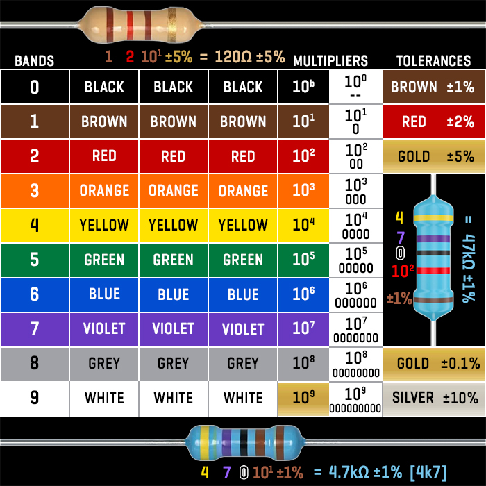
So as mentioned preciously, the current standard for THT Resistors tends to be either 4-Band or 5-Band.
Both use the same Colour-Coded Band System :
- Black = 0 | Non-Multiplier 100 / -
- Brown = 1 | Multiplier 101 / '0'
- Red = 2 | Multiplier 102 / '00'
- Orange = 3 | Multiplier 103 / '000'
- Yellow = 4 | Multiplier 104 / '0,000'
- Green = 5 | Multiplier 105 / '00,000'
- Blue = 6 | Multiplier 106 | '000,000'
- Violet = 7 | Multiplier 107 | '0,000,000'
- Grey = 8 | Multiplier 108 | '00,000,000'
- White = 9 | Multiplier 109 | '000,000,000'
For the final Tolerance [Band 4 or 5} value you have :
- Brown = ±1%
- Red = ±2%
- Gold = ±5% | ±0.1% for Thin Film Variants
- Silver = ±10%
As mentioned - there is a rare 6-Band standard too, where the 6th Band is a Temperature Coefficient :
- Brown = 100 ppm/oC
- Red = 50 ppm/oC
- Orange = 15 ppm/oC
- Yellow = 25 ppm/oC
- Blue = 10 ppm/oC
- Violet = 5 ppm/oC
For 4-Band Resistors you read them as follows :
- First Band = First Digit
- Second Band = Second Digit
- Third Band = Multiplier (Number of '0's)
- Fourth Band = Tolerance
In our Top Example above :
Brown = 1 | Red = 2 | Brown Multiplier = '0', Gold Tolerance = ±5% : so 120Ω
For 5 Band Resistors :
- First Band = First Digit
- Second Band = Second Digit
- Third Band = Third Digit
- Fourth Band = Multiplier (Number of '0's)
- Fifth Band = Tolerance
In our Bottom Example Above :
Yellow = 1 | Violet = 7 | Black = 0 | Brown Multiplier = '0', Brown Tolerance = ±1 : which can be referenced in 3 ways : 4700Ω / 4.7kΩ / 4k7 - all those references indicate the same value!
Common Effects Pedals Resistor Values
- 10kΩ : The single most frequently used value in pedal designs, found in biasing and gain stages
- 4K7Ω / 4,7kΩ : The second most common value, frequently used for voltage division and active biasing
- 1kΩ : Frequently used for LED Current Limiting and Simple Filtering
- 100kΩ : Standard Input / Output pull-down resistor value
- 1MΩ : Often used as pull-down resistors at the input/output to prevent popping noises when switching. Standard for high impedance input.
- Other common values include 2.2kΩ, 5.6kΩ, 47kΩ, 51kΩ, 470kΩ...
5. Key Functional Applications for Fixed Resistors
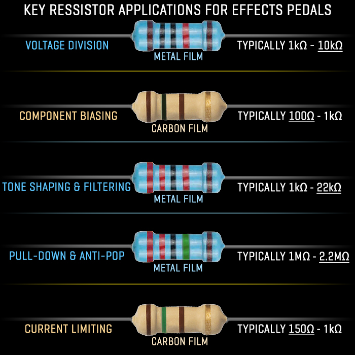
Here are 5 of the most typical Key Functional Applications for Resistors in Effects Pedal Circuits
A : Voltage Division
Using Resistor to lower the voltage coming from a power supply or passing through a signal path to match what specific parts of the circuit need.
Fixed Voltage Divider Resistors : 1kΩ / 10kΩ - Metal Film / Carbon Film
Vitalii notes - Using Resistors to lower the voltage coming from a power supply or passing through a signal path to match what specific parts of the circuit need - there are 2 common use cases : voltage divider as attenuation for audio (AC signals) (e.g. make signal a bit weaker to not overload the next gain stage/EQ, etc), and for DC signals (power supply dividers, most common virtual ground). For both cases typical values vary a lot, as actual resistance also affects output impedance and for VR - current. I would say typical range 10k - 1M. Examples include classic Rat VR 100k/100k, classic Distortion+ 1M/1M for VR, but usually 10k-47k.
B : Active Component Biasing
Using Resistor to feed exact amounts of voltage and current to transistors or op-amps so these active components operate in their optimal zones for amplifying or distorting the guitar signal.
Biasing Resistors : 100Ω to 1kΩ : - Metal Film / Carbon Film
Vitalii notes - this would vary significantly, depending on transistor vs OpAmp, etc. For transistor gain stages actually a voltage divider bias on base is more common (one resistor to ground, another to power line, other ends to transistor base), typical Si pair is likely 470k/100k. If it's a BJT / FET buffer or OpAmp buffer gain stage then it's usually resistor to VR before the stage and such a resistor for a non-inverting configuration also sets input impedance. Usually we will want quite high input impedance, so typical values are 100k - 2M2.
C : Tone Shaping and Filtering
When paired with capacitors, resistors create filters that block or pass specific frequencies (like cutting high-end hiss or boosting mid-range response).
Typical Tone Stack Resistors : 1kΩ to 22kΩ - Metal Film
Vitalii notes - when paired with capacitors, resistors create filters that block or pass specific frequencies - without semiconductors they are only passive filters (then a mid boost is not possible by definition). Passive filters are basically frequency-dependant resistors. and I can say there is a particular typical value - no problem to use 1k or 100k in filters.E.g. Rat passive lowpass at 1k5 fixed, and 100k variable resistance.
D : Pull-Down / Anti-Pop Resistors
High-value resistors (often 1MΩ) that tie idle signal paths to the ground to drain stray direct current (DC), stopping loud 'pops' when you stomp the footswitch.
Typical Anti-Pop Resistors : 1MΩ - 2.2MΩ - Metal Film
Vitalii notes - Cornish circuits sometimes use 10M for example, it usually also affects pedal input impedance too for input, but usually there are 100k - 470k resistors on the output for the same anti-pop purpose.
E : Current Limiting
Resistors control how much current flows into indicator LEDs so the lights shine safely without burning out or draining extra power.
Typical Limiter Resistor : 150Ω to 1kΩ - Metal Film / Carbon Film
Vitalii notes - for LED example at 9V, the most common resistor is 4k7 for the typical Red colour. also very common in pedal power supply stage to have a small 47R-100R current limiting + filtering resistor (filtering done with cap to ground). E.g. Rat has 47R current limiting resistor + 100uF to gnd.
6. Smart Resistor Deployments and Mods in Specific Circuits (Fuzz Face etc.)
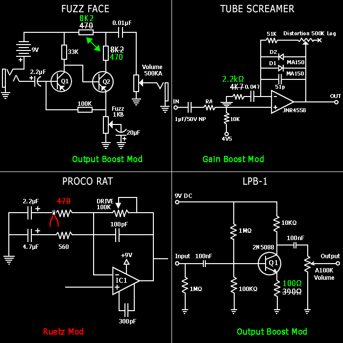
This section details 4 of the best known quick and easy Resistor Mods - which should be relatively easy for anyone with a soldering iron!
A : Fuzz Face Resistor-Swap Mod
The two end Resistors have values of 470 and 8K7. Which in vintage Arbiter Fuzz Faces makes for a lower output, To Boost the output - you simply swap those two Resistors around - so the 8K7 one goes in place of the 470, and the 470 goes in place of the 8K7.
B : Tube Screamer Gain Mod
Swap out the 4K7 Resistor for a lower value - say 2.2K as in our example, for a significant Boost to the Gain.
C : ProCo Rat Ruetz Mod
Probably the best-known Rat Mod - which consist of clipping one leg of or replacing the first 470Ω Resistor with a lower value - say 100Ω.
Cutting the Resistor entirely from the circuit means you loose the impact of the first Capacitor too. Vitalii and I aren't particular fans of the Ruetz Mod - as we both feels it somewhat 'neuters' the Rat's Output Profile. Vitalii recommends rather that your replace the 470Ω Reistor with a variable 1K Pot - which I tend to agree with!
D : LPB-1 Emitter Resistor Swap Mod
Here we simply swap out the 390Ω Resistor for a lower value one - say 100Ω. And in a similar way to example 'A' we get a significant Boost to the Output Level.
Note that you can do similar for any of the 4 Gain Stages of a Big Muff too! While lowering the Resistor Value too much can impact the character of the output - making it significantly rougher and grainier. Many go for more subtle value Mods - which preserve the smoothness of the core character - but just deliver more output volume.
The general prevailing wisdom is that for Big Muffs - you would typically only target a couple of the gain stages!
7. Resistor Circuit Examples
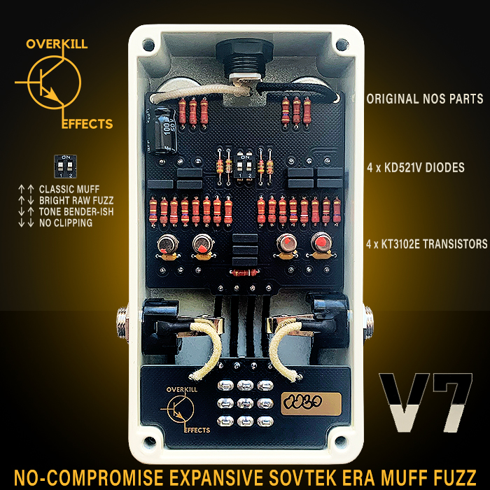
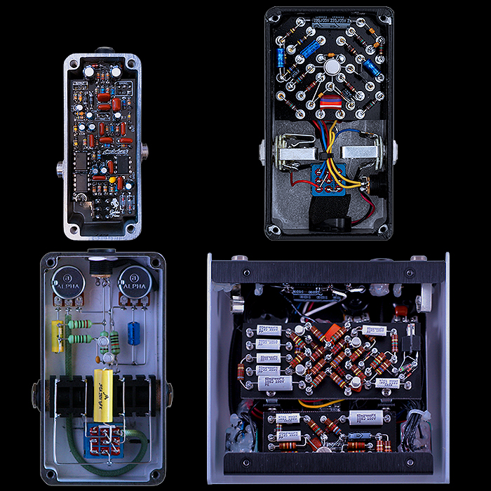

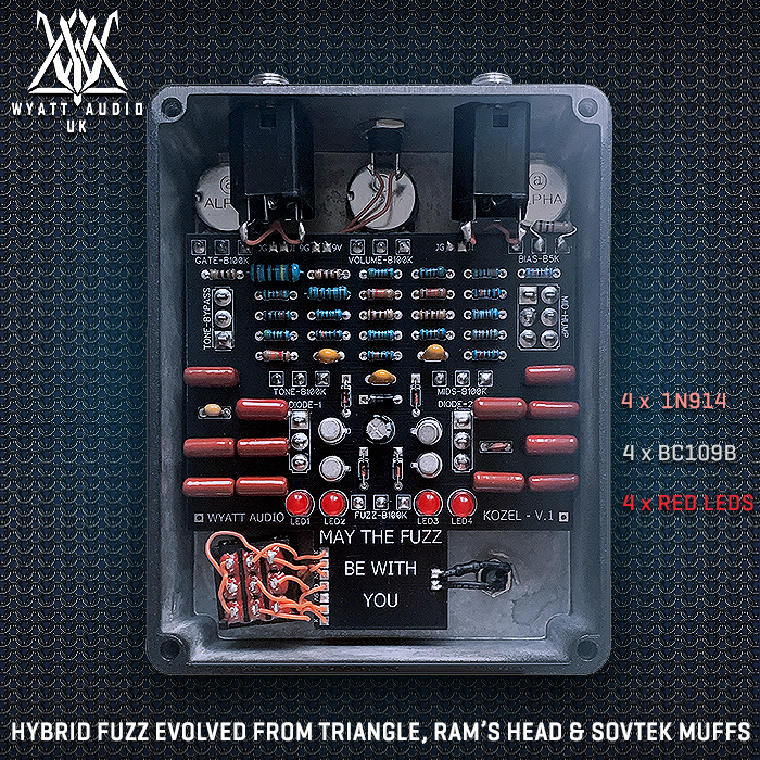



Posted by Stefan Karlsson


Content Alerts
Featured Articles




Profile
Stefan Karlsson
Guitar Pedal X
Feeds
News Navigation






4 of a Kind - Mini Plexi Style Overdrives
Nov 11, 2026


The Chase Bliss Mystery Box is Back!
Oct 22, 2026



Peterson launches StroboStomp EVH Edition Tuner with 13 Exclusive Eddie Van Halen Sweetened Tunings used on the debut 1978 Van Halen Album
"Thanks very much for sharing information about "...
1 day ago
Browne Amplification unleashes Unit-13 Dual Channel Low and High Gain Distortion - Inspired by and evolved beyond the Rat Distortion
"Yeah - it's a little over pricey for me too here "...
2 days ago

Browne Amplification unleashes Unit-13 Dual Channel Low and High Gain Distortion - Inspired by and evolved beyond the Rat Distortion
"I want one really bad but struggling with the $400"...
3 days ago
Susumu Tamura - the original creator of the Tube Screamer Pedal - makes the next evolution of that format for Totally Wycked Audio - as the new Source Code Overdrive - with unique 'Bite' control and refinements in every area
"I wasn't too sure about this pedal until I "...
4 days ago
3 mostly Brian May inspired Mini Pedals from Japan's Brian May experts Kz Guitar Works
"There's bound to be significant difference - the "...
6 days ago
3 mostly Brian May inspired Mini Pedals from Japan's Brian May experts Kz Guitar Works
"Hey Mik - I'm not really in a position to say "...
6 days ago
3 mostly Brian May inspired Mini Pedals from Japan's Brian May experts Kz Guitar Works
"I realize this might be a bit early to ask but "...
7 days ago
House Music Label Odyssey - My DJ'ing Years : 1988-2008
"Thank you Troy - Music has always been a very big "...
7 days ago
House Music Label Odyssey - My DJ'ing Years : 1988-2008
"Great article Stefan, I love all this stuff too, "...
7 days ago
Electro-Harmonix finally releases its Big Muff Pi Hardware Plugin with full Analogue Ram's Head Circuit at its heart
"Well at least we tried, sorry about that Stefan. "...
9 days ago

Related Articles